
1 / 5
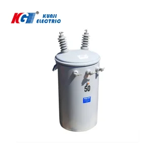
This specification provides for the design, manufacture, testing in factory, supply, delivery and off-loading on site for Pole Mounted Distribution Transformers. It shall be the responsibility of the Contractor to furnish equipment which shall meet in all respects the performance specification and will have satisfactory durability for the prevailing site conditions.
All equipment and materials shall be in full accordance with IEC (International Electrotechnical Commission) and ISO (International Standards Organisation) standards. Key standards include:
| Standard | Title |
|---|---|
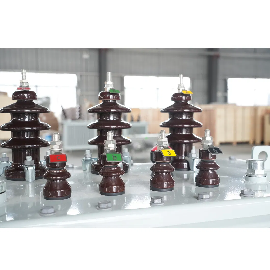
| IEC 60137 | Insulated bushings for AC Voltages above 1 kV |
| IEC 60076-1 | Power Transformers - General |
| IEC 60076-2 | Temperature rise |
| IEC 60076-3 | Insulation levels, dielectric tests and external clearances |
| IEC 60076-7 | Loading guide for oil immersed transformers |
| IEC 60296 | Specification for unused mineral insulating oils |
| Load % of Rating | Duration at 30°C Ambient (Min) | Duration at 40°C Ambient (Min) |
|---|---|---|
| 133% | 240 | 115 |
| 150% | 98 | 65 |
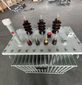
Core: High grade cold rolled non-aging grain oriented silicon steel laminations (Grade M4 or better).
Winding: High conductivity, non-oxidising solid drawn EC Grade copper. Concentric design for electromagnetic balance.
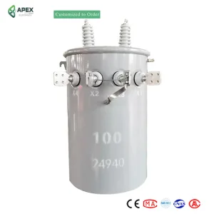
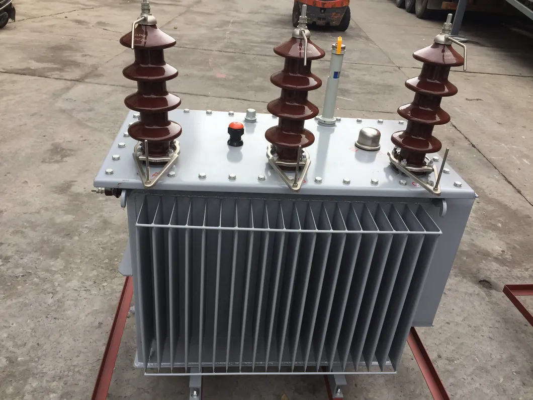
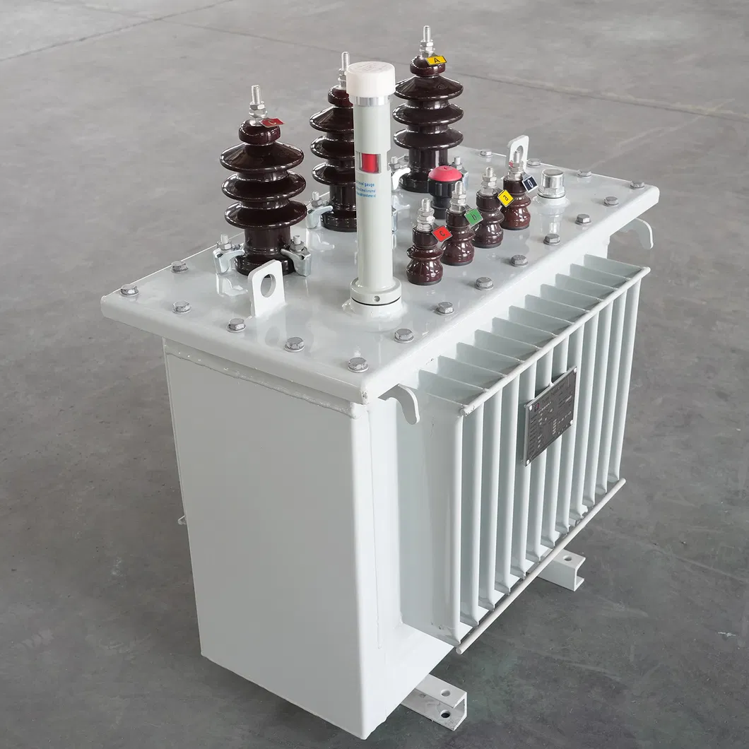
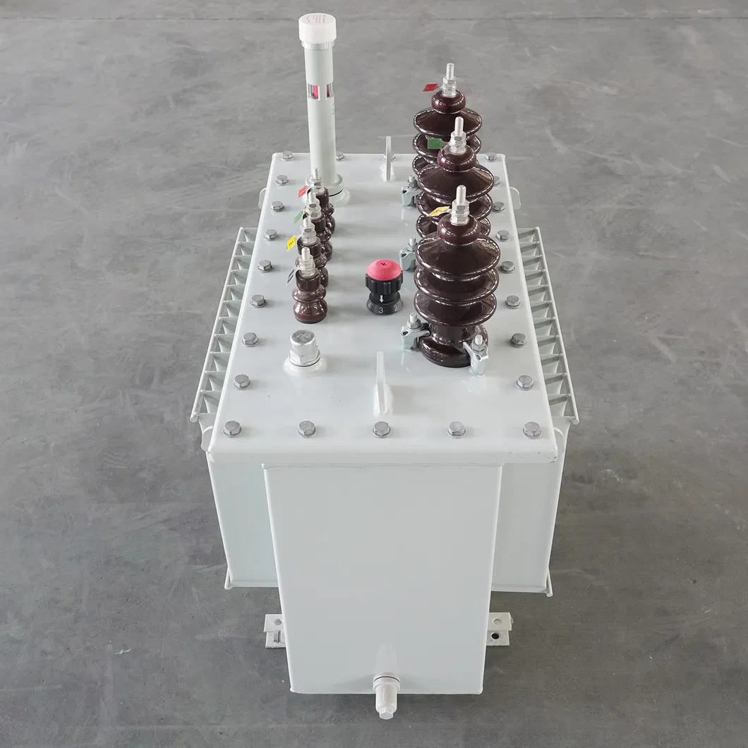
Tank: Hermetically sealed construction with 3mm minimum steel thickness. Hot dip galvanizing preferred for corrosion protection.
Insulation: Double paper covering for both HV & LV windings. Thermally stabilized paper or Class A.
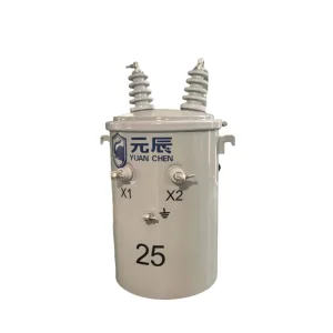
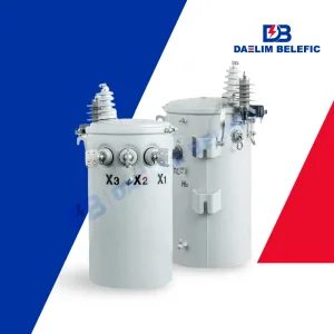
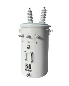
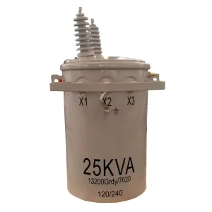
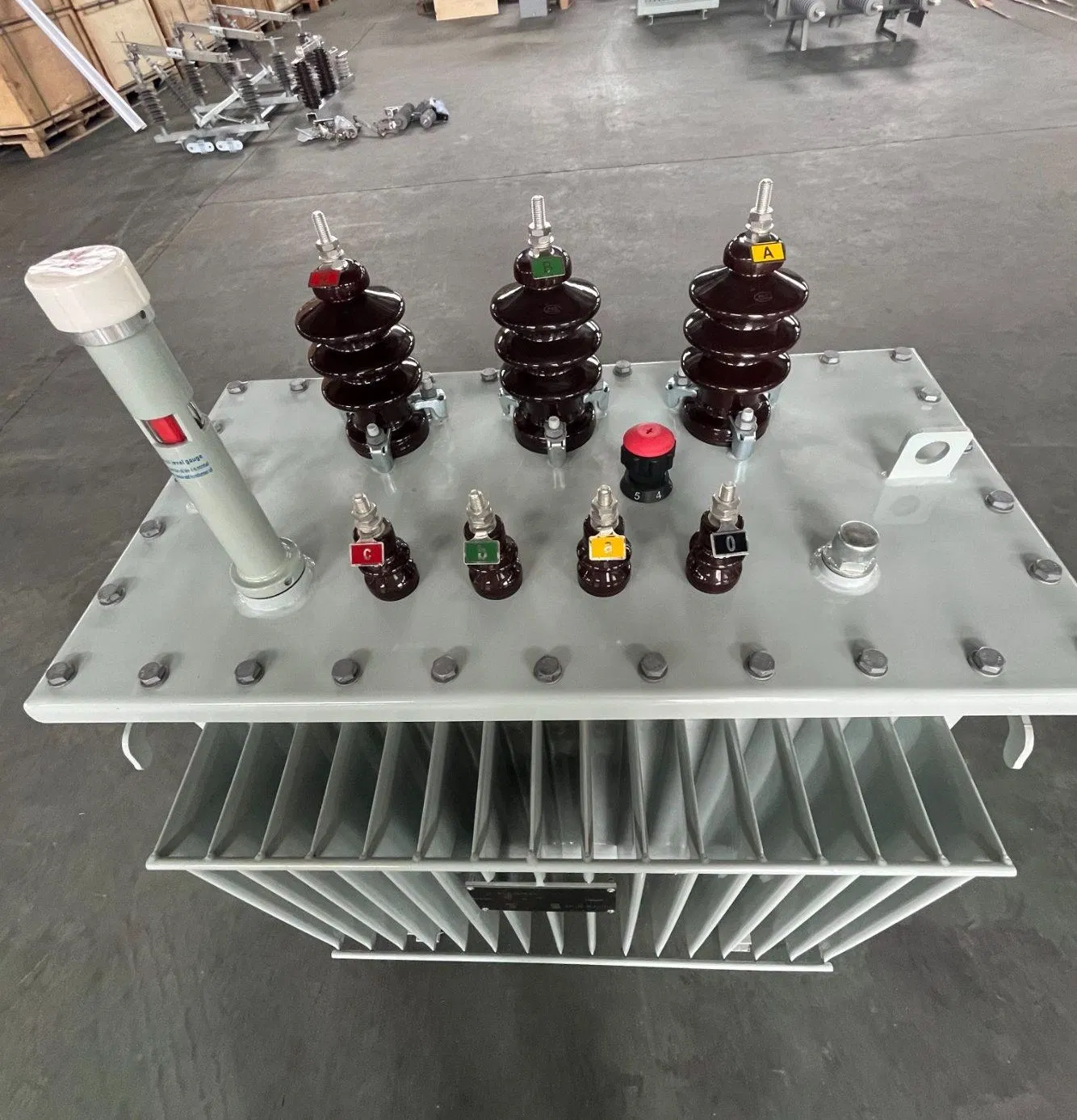
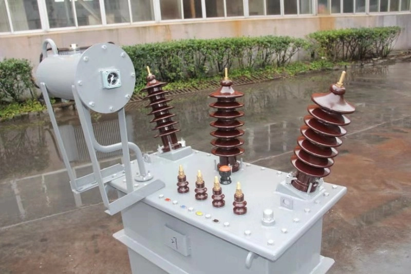
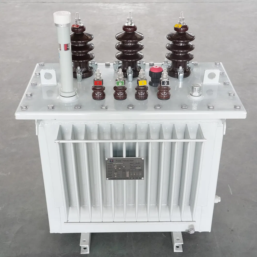
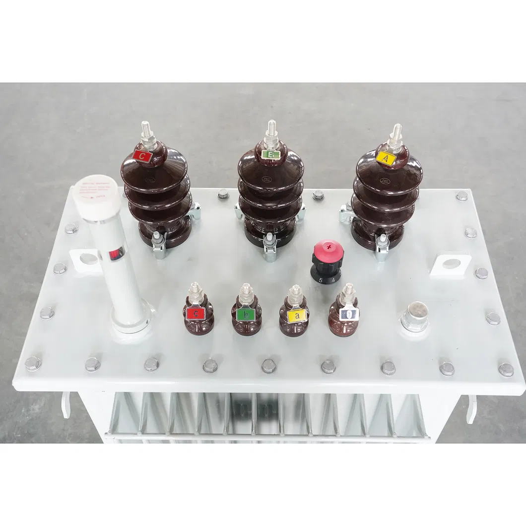
Units are equipped with: Off-load Tap Changer, LV/MV Bushings, Grounding Terminals, Pressure Relief Device (40kN/sq m), Oil Level Gauge, Lifting Lugs, and Filling/Draining Valves.
A1: These transformers are designed in full accordance with IEC (International Electrotechnical Commission) and ISO (International Standards Organisation) recommendations, specifically IEC 60076 for power transformers and IEC 60137 for insulated bushings.
A2: The flux density at any point of the magnetic circuit operating at normal voltage and frequency does not exceed 1.65 Tesla. Over-fluxing is limited to 12.5% to prevent core saturation.
A3: The tanks are preferably hot-dip galvanized. If not practicable, they are shot-blasted, zinc sprayed (minimum 550gm/m2), and finished with zinc chromate primary paint followed by weather-resisting Admiralty Grey paint.
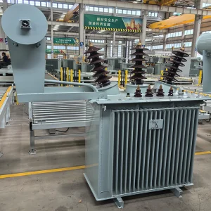
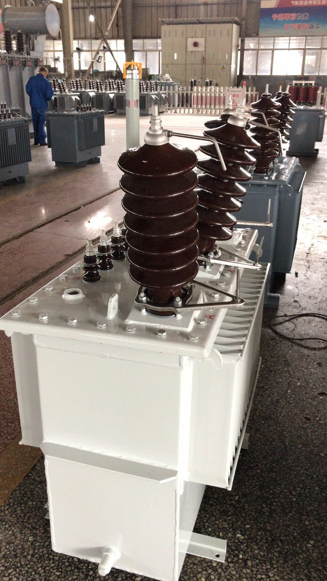
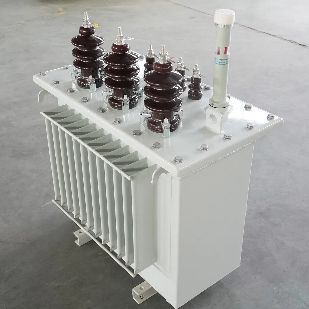
A4: These are naturally cooled (ONAN) units with oil-immersed copper windings, suitable for outdoor exposed locations.
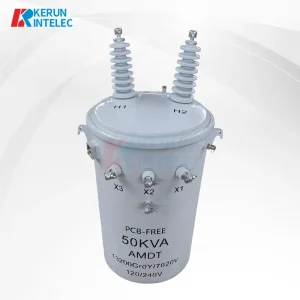
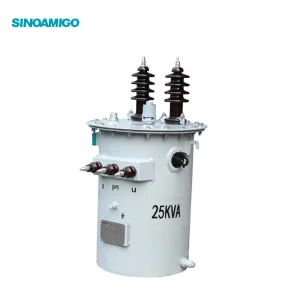
A5: A 5-position externally operated tap changer is provided on the MV winding, allowing for no-load primary voltage variation of +/-2.5% and +/-5%.
A6: For 33kV windings, the Basic Impulse Level (BIL) is 170kV and the Power Frequency withstand voltage is 70kV.